
Introduction
There are many different types of ignition systems. Most of these systems can be placed into one of three distinct groups: the conventional breaker point type ignition systems (in use since the early 1900s); the electronic ignition systems (popular since the mid 70s); and the distributorless ignition system (introduced in the mid 80s).
The automotive ignition system has two basic functions: it must control the spark and timing of the spark plug firing to match varying engine requirements, and it must increase battery voltage to a point where it will overcome the resistance offered by the spark plug gap and fire the plug.
The first step in understanding a vehicle's ignition system is to learn about basic electricity. For more information on electrical circuits, how they work and how to troubleshoot them, please refer to the information on "Understanding and Troubleshooting Electrical Systems" elsewhere in this manual.
How the ignition system works
Point-type ignition system
See Figures 1, 2 and 3
An automotive ignition system is divided into two electrical circuits -- the primary and secondary circuits. The primary circuit carries low voltage. This circuit operates only on battery current and is controlled by the breaker points and the ignition switch. The secondary circuit consists of the secondary windings in the coil, the high tension lead between the distributor and the coil (commonly called the coil wire) on external coil distributors, the distributor cap, the distributor rotor, the spark plug leads and the spark plugs.
The distributor is the controlling element of the system. It switches the primary current on and off and distributes the current to the proper spark plug each time a spark is needed. The distributor is a stationary housing surrounding a rotating shaft. The shaft is driven at one-half engine speed by the engine's camshaft through the distributor drive gears. A cam near the top of the distributor shaft has one lobe for each cylinder of the engine. The cam operates the contact points, which are mounted on a plate within the distributor housing.
A rotor is attached to the top of the distributor shaft. When the distributor cap is in place, a spring-loaded piece of metal in the center of the cap makes contact with a metal strip on top of the rotor. The outer end of the rotor passes very close to the contacts connected to the spark plug leads around the outside of the distributor cap.
The coil is the heart of the ignition system. Essentially, it is nothing more than a transformer which takes the relatively low voltage (12 volts) available from the battery and increases it to a point where it will fire the spark plug as much as 40,000 volts. The term "coil" is perhaps a misnomer since there are actually two coils of wire wound about an iron core. These coils are insulated from each other and the whole assembly is enclosed in an oil-filled case. The primary coil, which consists of relatively few turns of heavy wire, is connected to the two primary terminals located on top of the coil. The secondary coil consists of many turns of fine wire. It is connected to the high-tension connection on top of the coil (the tower into which the coil wire from the distributor is plugged).
Under normal operating conditions, power from the battery is fed through a resistor or resistance wire to the primary circuit of the coil and is then grounded through the ignition points in the distributor (the points are closed). Energizing the coil primary circuit with battery voltage produces current flow through the primary windings, which induces a very large, intense magnetic field. This magnetic field remains as long as current flows and the points remain closed.
As the distributor cam rotates, the points are pushed apart, breaking the primary circuit and stopping the flow of current. Interrupting the flow of primary current causes the magnetic field to collapse. Just as current flowing through a wire produces a magnetic field, moving a magnetic field across a wire will produce a current. As the magnetic field collapses, its lines of force cross the secondary windings, inducing a current in them. Since there are many more turns of wire in the secondary windings, the voltage from the primary windings is magnified considerably up to 40,000 volts.
The voltage from the coil secondary windings flows through the coil high-tension lead to the center of the distributor cap, where it is distributed by the rotor to one of the outer terminals in the cap. From there, it flows through the spark plug lead to the spark plug. This process occurs in a split second and is repeated every time the points open and close, which is up to 1500 times a minute in a 4-cylinder engine at idle.
To prevent the high voltage from burning the points, a condenser is installed in the circuit. It absorbs some of the force of the surge of electrical current that occurs during the collapse of the magnetic field. The condenser consists of several layers of aluminum foil separated by insulation. These layers of foil are capable of storing electricity, making the condenser an electrical surge tank.
Voltages just after the points open may reach 250 volts because of the amount of energy stored in the primary windings and the subsequent magnetic field. A condenser which is defective or improperly grounded will not absorb the shock from the fast-moving stream of electricity when the points open and the current can force its way across the point gap, causing pitting and burning
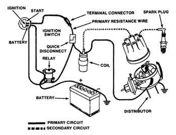
Figure 1 A schematic of a typical conventional breaker-point ignition system.
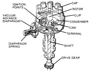
Figure 2 A conventional breaker-point distributor.
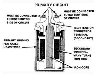
Figure 3 Cutaway view of a conventional coil.
The primary windings connect to the small terminals on the top of the coil,
while the secondary winding connects to the central tower.
Electronic ignition systems
See Figure 4
The need for higher mileage, reduced emissions and greater reliability has led to the development of the electronic ignition systems. These systems generate a much stronger spark which is needed to ignite leaner fuel mixtures. Breaker point systems needed a resistor to reduce the operating voltage of the primary circuit in order to prolong the life of the points. The primary circuit of the electronic ignition systems operate on full battery voltage which helps to develop a stronger spark. Spark plug gaps have widened due to the ability of the increased voltage to jump the larger gap. Cleaner combustion and less deposits have led to longer spark plug life.
On some systems, the ignition coil has been moved inside the distributor cap. This system is said to have an internal coil as opposed to the conventional external one.
Electronic Ignition systems are not as complicated as they may first appear. In fact, they differ only slightly from conventional point ignition systems. Like conventional ignition systems, electronic systems have two circuits: a primary circuit and a secondary circuit. The entire secondary circuit is the same as in a conventional ignition system. In addition, the section of the primary circuit from the battery to the battery terminal at the coil is the same as in a conventional ignition system.
Electronic ignition systems differ from conventional ignition systems in the distributor component area. Instead of a distributor cam, breaker plate, points, and condenser, an electronic ignition system has an armature (called by various names such as a trigger wheel, reluctor, etc.), a pickup coil (stator, sensor, etc.), and an electronic control module.
Essentially, all electronic ignition systems operate in the following manner: With the ignition switch turned on, primary (battery) current flows from the battery through the ignition switch to the coil primary windings. Primary current is turned on and off by the action of the armature as it revolves past the pickup coil or sensor. As each tooth of the armature nears the pickup coil, it creates a voltage that signals the electronic module to turn off the coil primary current. A timing circuit in the module will turn the current on again after the coil field has collapsed. When the current is off, however, the magnetic field built up in the coil is allowed to collapse, which causes a high voltage in the secondary windings of the coil. It is now operating on the secondary ignition circuit, which is the same as in a conventional ignition system.
Troubleshooting electronic ignition systems ordinarily requires the use of a voltmeter and/or an ohmmeter. Sometimes the use of an ammeter is also required. Because of differences in design and construction, troubleshooting is specific to each system. A complete troubleshooting guide for you particular application can be found in the Chilton's Total Car Care manual.
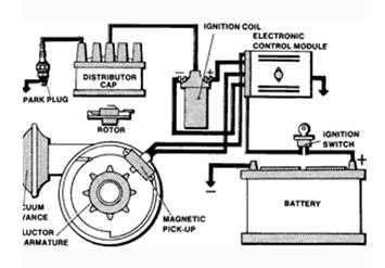
Figure 4 Typical electronic ignition system.
Note its basic similarity to a conventional system.
Distributorless ignition systems
See Figures 5 and 6
The third type of ignition system is the distributorless ignition. The spark plugs are fired directly from the coils. The spark timing is controlled by an Ignition Control Unit (ICU) and the Engine Control Unit (ECU). The distributorless ignition system may have one coil per cylinder, or one coil for each pair of cylinders.
Some popular systems use one ignition coil per two cylinders. This type of system is often known as the waste spark distribution method. In this system, each cylinder is paired with the cylinder opposite it in the firing order (usually 1-4, 2-3 on 4-cylinder engines or 1-4, 2-5, 3-6 on V6 engines). The ends of each coil secondary leads are attached to spark plugs for the paired opposites. These two plugs are on companion cylinders, cylinders that are at Top Dead Center (TDC) at the same time. But, they are paired opposites, because they are always at opposing ends of the 4 stroke engine cycle. When one is at TDC of the compression stroke, the other is at TDC of the exhaust stroke. The one that is on compression is said to be the event cylinder and one on the exhaust stroke, the waste cylinder. When the coil discharges, both plugs fire at the same time to complete the series circuit.
Since the polarity of the primary and the secondary windings are fixed, one plug always fires in a forward direction and the other in reverse. This is different than a conventional system firing all plugs the same direction each time. Because of the demand for additional energy; the coil design, saturation time and primary current flow are also different. This redesign of the system allows higher energy to be available from the distributorless coils, greater than 40 kilovolts at all rpm ranges.
The Direct Ignition System (DIS) uses either a magnetic crankshaft sensor, camshaft position sensor, or both, to determine crankshaft position and engine speed. This signal is sent to the ignition control module or engine control module which then energizes the appropriate coil.
The advantages of no distributor, in theory, is:
• No timing adjustments
• No distributor cap and rotor
• No moving parts to wear out
• No distributor to accumulate moisture and cause starting problems
• No distributor to drive thus providing less engine drag
The major components of a distributorless ignition are:
• ECU or Engine Control Unit
• ICU or Ignition Control Unit
• Magnetic Triggering Device such as the Crankshaft Position Sensor and the Camshaft Position Sensor
• Coil Packs
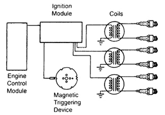
Figure 5 Typical distributorless ignition schematic.
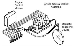
Figure 6 Components of a typical distributorless ignition system.
Ignition timing
See Figures 7 and 8
Ignition timing is the measurement, in degrees of crankshaft rotation, of the point at which the spark plugs fire in each of the cylinders. It is measured in degrees before or after Top Dead Center (TDC) of the compression stroke.
Because it takes a fraction of a second for the spark plug to ignite the mixture in the cylinder, the spark plug must fire a little before the piston reaches TDC. Otherwise, the mixture will not be completely ignited as the piston passes TDC and the full power of the explosion will not be used by the engine.
Ignition timing on many of today's vehicles is controlled by the engine control computer and is not adjustable. However the timing can be read using a scan tool connected to the data link connector.
The timing measurement is given in degrees of crankshaft rotation before the piston reaches TDC (BTDC). If the setting for the ignition timing is 5° BTDC, the spark plug must fire 5° before each piston reaches TDC. This only holds true, however, when the engine is at idle speed.
As the engine speed increases, the pistons go faster. The spark plugs have to ignite the fuel even sooner if it is to be completely ignited when the piston reaches TDC. To do this, distributors have various means of advancing the spark timing as the engine speed increases. On older vehicles, this was accomplished by centrifugal weights within the distributor along with a vacuum diaphragm mounted on the side of the distributor. Later vehicles are equipped with an electronic spark timing system in which no vacuum or mechanical advance is used, instead all timing changes electronically based on signals from various sensors.
If the ignition is set too far advanced (BTDC), the ignition and expansion of the fuel in the cylinder will occur too soon and tend to force the piston down while it is still traveling up. This causes engine ping. If the ignition spark is set too far retarded, after TDC (ATDC), the piston will have already passed TDC and started on its way down when the fuel is ignited. This will cause the piston to be forced down for only a portion of its travel. This will result in poor engine performance and lack of power.
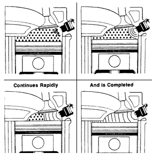
Figure 7 Normal combustion in the cylinder.
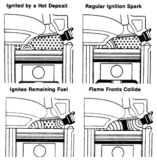
Figure 8 Preignition is just what the name implies
-- ignition of the fuel charge prior to the time of the spark.
Any hot spot within the combustion chamber, such as glowing carbon deposits,
rough metallic edges or overheated spark plugs, can cause preignition.
Ignition system maintenance
Electronic ignitions, of course, do not need distributor maintenance as often as conventional point-type systems; however, nothing lasts forever. The distributor cap, rotor and ignition wires should be replaced at the manufacturer's suggested interval. Also, because of the higher voltages delivered, spark plugs should last anywhere from 30,000-60,000 miles (48000-96500 Km).
For more information on vehicle electrical systems, please check out the lots more information in RIBO Parts Articles. 


