
Perhaps the most important tool you'll use in troubleshooting auto electrical systems is the multimeter. Basic multimeters measure voltage, current and resistance, while more elaborate multimeters, such as the Fluke 78, or Fluke 88 have features that can check things such as frequency, duty cycle, dwell, make diode tests, and even measure temperature, pressure and vacuum.
Starter Current
Starting system troubles are often confused with charging system problems. Many a dead battery has been replaced when the real cause was a faulty charging system. Be sure that the charging system is functioning properly before you replace the battery. Make sure the battery is charged and passes a load test, then look for resistance in the starter circuit if the engine still cranks slowly. Investigate excessive current draw; check for worn-through insulation, a seized or tight engine, a faulty starter, etc. If the starter turns the engine slowly, the current draw is not high, and the battery is in good condition, check the resistance in the starter circuit.
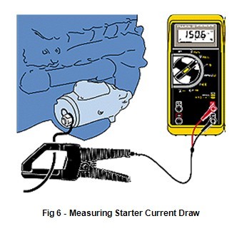
Determine how much current the starter is drawing by using Fluke's 80i-401, 80i-1010, or 90i-610s Inductive Current Clamp on the starter cable. This accessory will allow the multimeter to measure starter current up to 1000 amps. Check manufacturer's specs for exact figures.
Alternator AC Leakage
An alternator generates current and voltage by the principles of electromagnetic induction. Accessories connected to the vehicles charging system require a steady supply of direct current at a relatively steady voltage level. You can't charge a battery with alternating current, so it must be rectified to direct current.
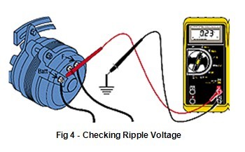
Ripple voltage or (AC voltage) can be measured by switching your DMM to AC and connecting the black lead to a good ground and the red lead to the "BAT" terminal on the back of the alternator, (not at the battery). A good alternator should measure less than .5 VAC with the engine running. A higher reading indicates damaged alternator diodes.
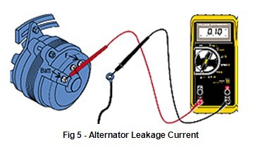
To check alternator diode leakage, connect the multimeter in series with the alternator output terminal when the car is not running. Leakage current should be a couple of milliamps at most; more often, it will be on the order of 0.5 milliamps. Use care when disconnecting the alternator output wire; make sure the battery is disconnected first.
Alternators
A DMM's accuracy and digital display make regulator/alternator diagnosing and adjusting easy. First determine if the system has an integral (internal) regulator, then whether it's type A or B. Type-A has one brush connected to battery + and the other brush grounded through the regulator. Type-B has one brush directly grounded and the other connected to the regulator.
Next, isolate the problem to alternator or regulator by bypassing the regulator (full-fielding). Ground Type-A field terminal. Connect Type-B field terminal to Battery +. If the system now charges, the regulator is faulty. Use a rheostat if possible. Otherwise, just idle the engine (lights on) so the voltage doesn't exceed 15V.
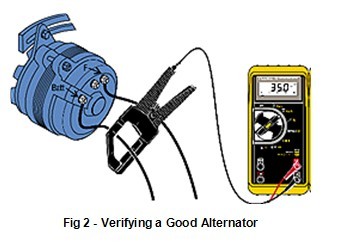
The battery must be fully charged (see fig. 1). Run the engine and verify that no-load voltage is 13.8 - 15.3V (check as in fig. 1). Next, load the alternator to rated output current with a carbon pile across the battery. Run the engine @ 2000 RPM. Check the current with an 80i-410 or 80i-1010 current clamp. The unit must maintain at least 12.6V @ rated output.
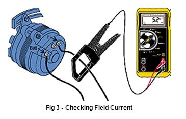
Worn brushes limit field current, causing low alternator output. To test: load unit as in Figure 2 and measure field current with current clamp or use 10A jack on DMM. Readings range from 3 to 7 amps. On integral GM units: with alternator not turning, jump terminals #1 & #2 (fig. 4) together and connect both to Batt + with DMM in series set to measure 10 amps. Field current should be between 2 & 5 amps, higher current with lower battery voltage. Control battery voltage by loading it with a carbon pile.
Batteries
Charging system problems often come to you as a "no-start" complaint. The battery will have discharged and the starter won't crank the engine. The first step is to test the battery and charge it if necessary (fig 1).
No-Load Test
Voltage Percent Charge
12.60V to 12.72V 100%
12.45V 75%
12.30V 50%
12.15V 25%
Readings obtained at 80°F (27°C)
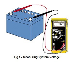
Bleed the surface charge from the battery by turning on the headlights for a minute. Measure the voltage across the battery terminals with the lights off (see chart). When possible, individual cell specific gravity should be checked with a hydrometer. A load test should be done to indicate battery performance under load. Voltage tests
Feedback Carburetor
Using the Fluke 78's built-in dwell meter to measure M/C dwell can tell you whether it's a fixed or varying cycle:
Fixed dwell occurs in several instances: 1) when the engine is in open loop (cold engine) 2) the engine is under wide-open throttle (hot engine) 3) the oxygen sensor has cooled off, due to prolonged idling, and re-entered open loop (hot engine).
Varying dwell tells you the engine is in closed loop. It also indicates whether the carburetor is supplying a rich or lean mixture.
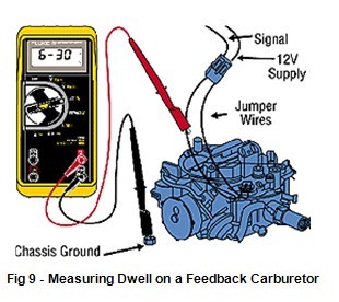
The longer the solenoid's "on-time," the higher the dwell -and the leaner the fuel mixture delivered by the carburetor. The shorter the "on-time," the lower the dwell -and the richer the fuel mixture. A normally operating system will have a varying dwell, but it should average about 30%.
Circuit Resistance
Ohm's law (E=IxR) tells us that even very low resistance in the starter circuit will cause the starter to turn slowly, because of low voltage. For example: in a system drawing 200 amps, 0.01 ohms resistance in the starter cable will cause a 2 volt drop in voltage at the starter; 0.01 ohms is too little for all but the most expensive and sophisticated ohmmeters to measure, but measurements of voltage drop will indicate where there is resistance.
Voltage Drop
In automotive circuits even the smallest loss of voltage will cause poor performance. Set your Fluke multimeter in the mV or VDC setting and connect the meter + lead to the side of the device nearer the battery + terminal and the - lead to the side nearer the battery - terminal or ground and engage the Min/Max function. Current must be flowing for the meter to register the voltage drop found. This procedure is helpful on components and connections (both on the + feed side and - ground side) except solenoids, which read battery voltage if you measure across them when the engine is being cranked.
Voltage drops should not exceed the following:
200 mV Wire or cable
300 mV Switch
100 mV Ground
0 mV to <50 mV Sensor Connections
0.0V Connections
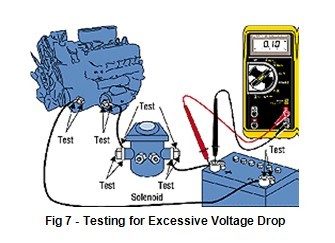
Determine if there is resistance in the circuit by measuring the voltage drop across each connection and component in the starter circuit while cranking the engine. Measure the voltage drop between the battery post and the connecting cable, the solenoid posts and the wires that attach to them, and across the solenoid itself. Also check the connection on the starter, alternator (feed and ground side) and the ground strap connection to the engine block and body.
Condensers
Fluke analog/digital multimeters can also be used for checking automotive capacitors (condensers). The movement of the bar graph will show that the DMM is charging the condenser. You'll see the resistance increase from 0 to infinity. Be sure the switch the leads and check both ways. Also make sure to check condensers, both hot and cold.
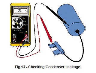
Check for leaking condensers with the Ohms function. As the condenser charges up, the resistance should increase to infinity. Any other reading indicates that you should replace the condenser.
Cooling Systems / Temperature Measurement
The Fluke 78's built-in temperature function makes it quick and easy to check engine cooling systems for proper temperature, which is critical with today's computer-controlled engines. You can also check transmissions for overheating, and heaters and air conditioning systems for proper operation. With the Fluke 78's bead thermocouple probe, you can test thermostats and fan switches without heating them in hot water on a hot plate. You get faster, more accurate diagnosis of electrically controlled cooling systems and can compare computer data stream information with actual temperatures. On many late model cars the cooling system is sealed; the only opening is in the expansion tank. Since it doesn't have water circulating through it, you can't make an accurate temperature measurement here. The only accurate test is to measure the surface temperature of the upper tank at the radiator inlet. With the Fluke 78, it's easy to do.
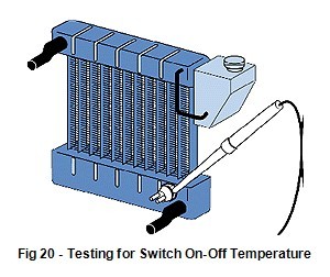
Check the operation of electric cooling fans by touching the radiator tank next to the temperature switch with the temperature probe tip. Note the temperature when the fan comes on, and again when it goes off. Check your figures against factory specifications.
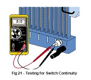
Check temperature-switch continuity with the Ohms function, while the switch is in place. Test for voltage drop across the switch and from the radiator to the body ground, as described on page 8. Note: the temperature must be above the "fan-on" temperature for the fan switch to be closed.
Locating Current Drains
Current drains, shorts and bad grounds are the cause of many problems. The cause of the problem often seems to have nothing to do with the symptom. But, using a DMM, you can find the cause quickly without burning a whole box of fuses. Current drains that run the battery dead are often referred to as shorts, although they may not actually be short circuits. In fact, they may be related to Keep Alive Memory or K.A.M. Shorts that blow fuses can be found using the same troubleshooting techniques used to find current drains even though the symptoms are different. CAUTION-Each vehicle manufacturer has a different procedure for locating current drains. Using the wrong testing method will give you erroneous results. To make sure you get the proper results, please refer to the vehicle manufacturer’s procedure.
Duty Cycle
Duty cycle is the measurement made of pulse width modulated circuits, such as a charcoal canister purge solenoid. The higher the duty cycle, the longer the on-time of that circuit. The higher the on-time, the higher the flow rate, or purging of the canister. 100% duty cycle means the solenoid is on all the time. 10% duty cycle means that the circuit is energized only a small portion of the time. The ECU determines when to purge the canister and at what flow rate based upon such variables as engine temperature, how long the engine has been running since startup, vehicle speed and other parameters.
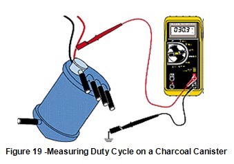
To measure the duty cycle of a solenoid, attach the red lead to the signal wire and the black lead to a good engine ground. Select duty cycle and read the value directly.
Ford BP/MAP Sensor
The barometric pressure/manifold absolute pressure (BP/MAP) sensor is critical in determining fuel mixture and spark advance under varying loads. Much like a Throttle Position Sensor, it must provide a smooth, gradual change in output, or driveability problems can occur. In some instances, a BP/MAP sensor can deviate without setting trouble codes. To verify its operation, you need to check its output over its full operating range.
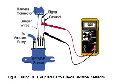
To test the performance of a BP/MAP sensor, graph its frequency output at various levels of vacuum. Start with the sensor at 0" Hg (0 cm /hg) and read its frequency. Then note the frequency at each increase of 1" Hg (cm Hg). When you plot these frequencies, they should be in a straight line. The frequency will decrease with an increase in vacuum.
Fuel Pressure
Fuel pressure is important for both performance and fuel efficiency. Maintaining proper fuel pressure under all operating conditions is the job of the fuel system. The PV350 provides critical fuel pressure readings on a multitude of fuel systems: carbureted, central point, throttle body injection or multipoint injection. Use it with the Fluke 78 to check the operation of fuel pressure regulators, fuel pumps and fuel pump check valves. Fuel pressures fall into two categories: high and low. Central point, or throttle body systems typically use low pressure (10-15 psi, 70-105 kPa). Most multipoint systems use a higher pressure (35-60 psi, 240-415 kPa). Low pressure during hard acceleration can indicate that a fuel filter is starting to clog.
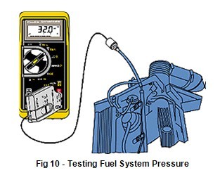
To test fuel pressure, use the schrader hose adapter with the PV500 to tap into the fuel rail. (If the vehicle doesn't have a schrader valve port, ask your local tool supplier for the appropriate adapter). Once you've taken your reading and before disconnecting the fitting, wrap a rag around it to catch any fuel spray. The safest way to do this is to disable the fuel pump and run the engine until it dies. Crank the engine a few seconds longer until all fuel pressure is relieved.
Rear Window Grid Defogger
Fluke DMMs allow you to check for opens in the rear window defroster grid. The rear window glass has a series of horizontal grid lines made of a conductive ceramic silver compound that are baked onto the inside surface of the glass. Terminals are soldered to two vertical conductors called bus bars on each side of the glass; one serving as the feed connection (battery voltage) and the other as the chassis ground. Current flows through a relay to the rear grid when both the ignition switch and the rear window grid switch are turned on, usually drawing about 20 amps. (A portion of the grid can be damaged by scratching the inside of the window usually by placing items on the package shelf.) When the circuit of any horizontal grid is interrupted, no current will flow and that particular grid will not heat up. By determining where the open is, you can repair it with a grid repair kit.
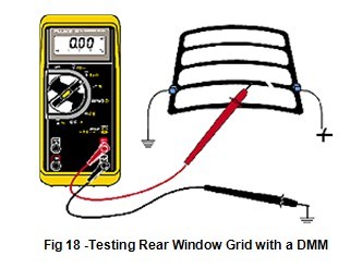
Run the engine at idle and set the rear window grid switch to "ON". Connect the black lead from your DMM to one of the vertical "bus bars" and the red lead to the other bus bar. With the meter set to measure DC volts, the display should indicate 10 to 14 volts; a lower reading indicates a loose ground wire. With the black lead of the DMM grounded, touch each grid wire at its midpoint with the red lead. A reading of approximately 6 volts identifies a grid with no opens. A reading of 0 volts indicates the current path is broken between the midpoint and the battery side of the grid. A reading of 12 volts indicates that the circuit is open between the midpoint of the grid line and ground.
Bad Grounds
High resistance among grounds can be among the most frustrating of electrical problems. They can produce bizarre symptoms that don't seem to have anything to do with the cause, once you finally find it. The symptoms include lights that glow dimly, lights that come on when others should, gauges that change when the headlights are turned on, or lights that don't come on at all.
With the new computer systems, high resistance in ground wires and sensor leads can produce all sorts of unpredictable symptoms. Apply silicone dielectric lubricant, available at radio supply stores, to connections before you assemble them. This will reduce corrosion. Pay particular attention to ground terminals in the vicinity of the battery, where acid speeds corrosion. Often a wire that is corroded through except for a few strands will produce the same symptom as a corroded ground connection. Just looking at the insulated connector does not insure that the connection inside is good. Physically disconnect connectors and use a wire brush or sand paper to "shine" the metal connections.
Hall-Effect Position Sensors
Hall-Effect position sensors have replaced ignition points in many distributors and are used to directly detect crank and/or cam position on distributorless ignition systems (DIS), telling the computer when to fire the coils. Hall-Effect sensors produce a voltage proportional to the strength of a magnetic field passing through them, which can come from a permanent magnet or an electric current. Since magnetic field strength is proportional to an electric current, Hall-Effect sensors can measure current. They convert the magnetic field into millivolts that can be read by a DMM.
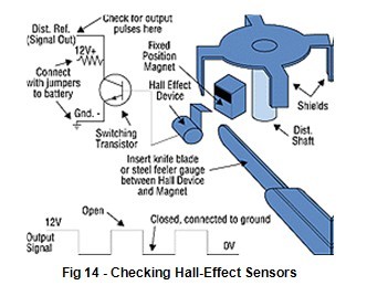
Check for reference voltage from battery at connector. Hall sensors require power where magnetic sensors do not. To test sensor: connect +12V from battery to power terminal, set DMM to measure volts and connect it between signal output and ground. Insert feeler blade between sensor and magnet while watching for the bar graph to move. Signal should vary from 12V to 0V.
Ignition Coils
Fluke analog/digital multimeters will measure from tenths of an ohm (.01_ on the Fluke 88) up to 32 million ohms, making ignition tests easy to interpret. Analog meters usually can't measure less than 1 ohm.
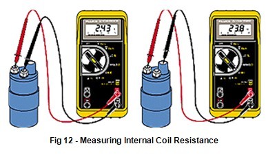
If you suspect a malfunctioning ignition coil, check the resistance of primary and secondary windings. Do this when the coil is hot, and again when it is cold. Also measure from the case to each connector. The primary windings should have a very low resistance, typically from a few tenths of an ohm to a few ohms. The secondary windings have a higher resistance, typically in the 10,000 to 13,000 ohm range. To get the actual figures for a specific coil, check the manufacturer's specs. But as a rule of thumb, primary windings range from a few tenths of an ohm to a few ohms, and secondary winding may be 10 ohms or more.
Magnetic Position Sensors
The magnetic type of position sensor is simply a magnet with a coil of wire wrapped around it. The clearance between the pickup and reluctor is critical. Be sure to check it. Specs are usually between 0.030" and 0.070" (0.8 mm to 1.8 mm).
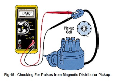
Disconnect the distributor from the ignition module. Connect the DMM across the pickup and set it to AC volts. When the engine is cranked, pulses should appear on the bar graph. If no pulses appear, it is likely the reluctor wheel or the magnetic pickup is faulty. Use this technique for other magnetic position sensors too. On GM cars, remove the distributor cap for access.
Example of Ohm's Law
If you measure 0.5V across a ground connection in a starter circuit, and the starter draws 100 amps, calculate the resistance as follows:
Ohm's Law E = I x R
0.5V = 100A x R
Solve for R
0.5V
R=100A
Therefore R = .005 Ohm
.005 ohm is too much, so clean the connection. .5 Volts tells you the same thing―the connection is dirty or corroded.
RPM
The RPM80 Inductive Pickup accessory allows the Fluke 78 to measure engine RPM via the secondary ignition impulses in the spark plug wires. It features a selection for DIS or conventional systems.
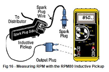
The RPM80 Inductive Pickup converts the magnetic field created by the current in the spark plug wire to a pulse that triggers an RPM measurement. To measure RPM using the pickup, attach the probe to any accessible sparkplug wire and select the normal (1) or DIS (2) setting to read the correct RPM for the engine you are working on.
Spark Plug Wires
Plug wires should be checked if your scope indicates that there may be a problem or if they're more than a couple of years old. Not all wires indicate the date they were manufactured. Due to the heat of the spark plug insulator, a spark plug boot may bond to the spark plug. Pulling a spark plug boot straight off the spark plug can damage the delicate conductor inside the insulated wire. Rotate the boot to free it before pulling it off. If you suspect bad wires, test the resistance of the wire while gently twisting and bending it. Resistance values should be about 10,000 ohms per foot ( 30,000 ohms per meter), depending on the type of wire being tested; some may be considerably less. You should compare readings to other spark plug wires on the engine to insure the accuracy of the test.
Throttle Position Sensor (TPS)
Throttle position sensors (TPSs) are a common source of faults in today's on-board computers. A TPS is simply a variable resistor connected to the throttle shaft. Some people think of it as a replacement for an accelerator pump on throttle body or port fuel injected engines. But it is much more. It tells the on-board computer how far the throttle is open, whether it is opening or closing―and how fast. As its resistance changes, so does the voltage signal returning to the computer. The TPS can be tested by watching either the voltage or resistance change, using the analog pointer on any Fluke DMM.
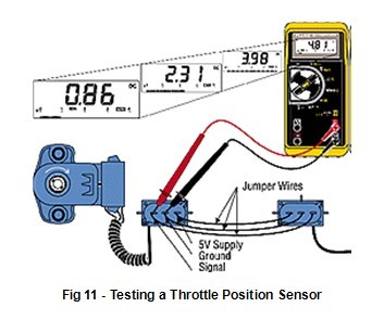
Use the Min/Max recording feature of the Fluke 78 to check your base TPS setting at idle; to get the maximum reading, depress the accelerator. By comparing these readings to those you get when you open the throttle by hand, you can verify whether the throttle cable and/or linkage is properly adjusted to allow full throttle opening. If it isn't, this may be the source of a problem with poor acceleration.
» More Information 


