AUTOMOTIVE ELECTRICAL THEORY
There's nothing difficult about electrical systems. The basic theory of electricity is simple and easily understood if you are just a little patient and curious. So, we're going to start off with a few definitions. Armed with an understanding of the following six terms, you will quickly learn to "think like an electron". Take your time and read these over until you understand the concept fully:
Electron: The basic unit of electricity. Think of these little guys as "bullets", traveling down the wire. It's the movement of electrons which runs the devices which make our lives - and our cars - so comfortable and convenient.
Voltage: This is the force (or pressure, if you like) of electricity in the wire. If you think of your garden hose as the wire, the water pressure would be equivalent to the voltage. Older cars run on six volt systems and newer (most 1956 and later) utilize twelve volt systems. All vehicles' manuals specify the system voltage.
Current: This is the movement of electrons in the wire, expressed in a unit called the Amp. The greater the rate of movement through the wire, the greater the number of amps. Think of this as the speed of the water coming out of the garden hose. When you tighten the nozzle the water shoots out further and faster.
Resistance: This is a restriction to the movement of electrons through the wire or circuit. The unit of resistance is called the OHM and you can think of it as a kink in that garden hose. The higher the resistance, the more current must flow to overcome it.
The more current which flows through an area of high resistance, the hotter the wire will become, ultimately failing. Corrosion, loose terminals and too-small diameter wires are three very, very common causes of resistance.
IMPORTANT FACT! High resistance is the cause of ALL electrical failures - with the exception of broken wires and lack of grounding - both of which will be discussed later.
Watts: The unit of power in electricity and the product of Amps x Volts. Why is this important? Because designers of circuits need to know the amount of current required for a given device (such as a fan, horn, light, etc.) in order to figure out which diameter wire to use. Example: a 50-watt brake light, operating on 12 volts, will draw 4.1 amps (4.1 amps x 12 volts = 50 watts). The wire diameter must be large enough to carry the current without heating up and melting off its insulation.
IMPORTANT FACT! This is the only formula you will ever really need to understand basic electricity, be it in your car or in your house.
Ground: All electrical devices must be part of a circuit. That is, electrons must flow from the power source through the device to a ground. In cars, the metal chassis is the ground (that's why the battery's negative lead is bolted to the engine or frame) and the power source is the positive lead on the battery. Without a ground there is only a POTENTIAL circuit. No electrons will flow - and therefore nothing will work - unless the circuit ends in a ground. Note: Some cars and trucks utilized "positive ground" electrical systems, where the positive lead from the battery connects to the frame and the negative lead goes to the electrical wiring harness. This in no way makes it more difficult to wire or troubleshoot; all that's required is to remember that the system is the reverse of normal systems.
STOP! DON'T READ ANY FURTHER UNTIL YOU REALLY UNDERSTAND ALL THE TERMS LISTED ABOVE!
Ready to go on? Okay, let's start with the fact that all cars run on Direct Current (DC) electrical systems, as opposed to alternating current (AC) which runs your home. DC is a "single wire" system. That is, the flow of electricity always runs from the source of current through the device and then to ground. It may do this through any number of connections and through other devices, but tracing the path is straightforward if you always ask the question:
"Where is the power coming from and is there a path to ground?"
For practical purposes, the flow of electricity is now considered to be from positive (voltage, designated by a plus sign +) to negative (ground, designated by a minus sign - ). Therefore, your car's battery "negative" terminal is connected to the metal framework of the car (some older cars - mostly foreign - utilized 'positive ground' systems but this is no longer done).
Tool Time!
In order to measure voltage, resistance, direction of current flow and other electrical parameters you need a multimeter. These are devices which have been around for many years and are available at electronics stores and even most home centers.
Inexpensive ($30 or so), reasonably high-quality meters are all the average hobbyist needs, so don't overspend. All these meters can measure DC, AC, resistance and even small amounts of current. Meters in this price range are fully capable of measuring your car's components accurately, as well as your household system and you can choose either analog or digital types, depending upon whether you like to read a dial or just a number display. After you purchase one, read the instructions and practice measuring voltages and resistances with it. An hour's practice should make you an expert. When you get accustomed to using a multimeter you will quickly come to appreciate its enormous versatility.
Battery:
Since the source of electricity in a car is the battery, let's see how one works:
A battery is an electrochemical device which converts chemical energy into electrical energy. Cars use "lead-acid" batteries.
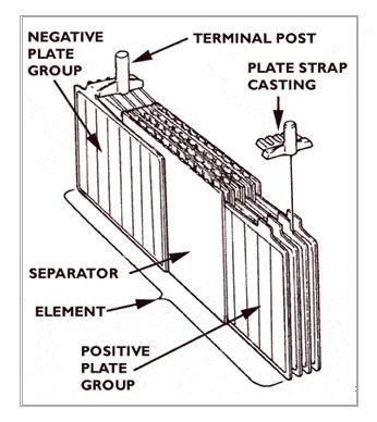
A lead-acid battery uses a series of lead dioxide plates for its positive (+) terminal and porous, soft lead for its negative plates. All the plates are arranged alternately and submerged in a solution of sulfuric acid and water. The positive plate's lead oxide is a compound of lead and oxygen. Sulfuric acid is a compound of hydrogen and the sulfate radical (SO4), so the acid's chemical designation is H2SO4.
Chemically, when a battery is connected to an external load (a device which uses electricity) it begins to discharge. As that happens, the lead in the positive plate combines with the sulfate of the acid, forming lead sulfate (PBSO4) in the positive plate. Oxygen in the positive plate combines with hydrogen from the acid to form water (H2O), which reduces the concentration of the acid in the electrolyte. Also, the pure lead in the negative plate combines with the sulfate, forming lead sulfate and making the positive and negative plates more alike in chemical composition. Electrons are released during this reaction, creating electric current at a specific voltage (2 volts per cell, with 6 cells in a 12-volt battery, described below).
The battery voltage depends upon the chemical difference between the two plate materials and the concentration of the acid. Because the plates have become more chemically alike and the electrolyte concentration has become weaker, the voltage output gets weaker and weaker until the battery is "dead", or discharged.
However, the battery can be re-charged by passing an electrical current through it in the opposite direction of the discharge. The chemical reactions during a charge cycle are the reverse of those that occur during discharge. As the battery is charged the positive plates become lead dioxide again, the negative plates become pure lead again and the electrolyte returns to its proper concentration. The charge-discharge cycle can be repeated over and over again, until fatigue and erosion of the electrodes and corrosion of the positive plates cause eventual failure.
Mechanically, batteries are composed of multiple "cells", each containing the positive and negative plates. A single cell will produce two volts, so your 12-volt battery has six cells grouped together in one case, for efficiency. The cells are connected in "series", or positive to negative to positive to negative; and so-on. When you connect something in series you add up each cell's voltage to get the overall battery's output.
So why does such a big, heavy thing like a battery only produce 12 volts? Well, it's the current (remember?) which does the work and all those plates immersed in that acid are capable of producing impressive amounts of amps, at least for short durations. A typical battery delivers 500-1000 amps and you need all that current to run the starter motor, not to mention other things.
Batteries fail to provide sufficient current generally in only a few ways:
1. The electrolyte and plates "wear out". The life of a battery (36 months, 48 months, etc.) is determined by the thickness and number of plates and you get what you pay for in that regard. Eventually the battery wears out and can't hold a charge. To test for this, have a service station test the cells with a hygrometer (a device which measures specific gravity ) or buy one for yourself (they're cheap). If the hygrometer says the battery is shot and it won't hold a charge, replace it.
2. The most common failure of batteries is loose or corroded cable connections. In either case, the reason for failure is HIGH RESISTANCE! (remember, a poor mechanical connection means that little or no current can pass through). If the cables are loose, tighten them thoroughly. If corroded, remove them and clean them with a file or sandpaper (clean both the cable connectors and the terminals!) It's a good practice to clean the connections at least once a year.
3. Overcharging, either through external chargers or faulty regulator, kills batteries by creating so much heat (due to current flow) that the water in the electrolyte is boiled off. In some cases the battery explodes. Of course, connecting jumper cables incorrectly can result in a dead short, with catastrophic consequences (A dead short is when all the current from the voltage source is connected directly to ground without passing through any device or resistance. In the case of a battery, it would be equivalent to connecting both terminals together, causing a huge current flow through the plates, in turn causing massive heating, then boiling, and finally the battery will blow up).
GENERATORS AND ALTERNATORS
Last month's article dealt with the principles of DC electricity and how your car's battery functions. Now we can go on to how that battery gets charged. In older cars (before about 1964) this was done with a generator. After that time all cars switched to alternators and the reasons for the change will become clear. Let's see how each works. First, the generator:
The basic principle at work here is that electricity produces magnetism. Conversely, magnetism produces electricity. If a current-carrying coil of wire is placed around a bar of steel, the bar will become magnetized. The more turns of wire and the stronger the current, the more powerful the magnet. By placing a soft iron core within the coil, the magnetic force lines are concentrated and strengthened. As there is less electrical resistance (remember resistance?) in the iron than in the surrounding air, the force lines will follow the core.
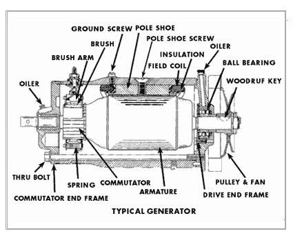
The two pole shoes of a generator are constructed in this way. Rather than use magnets - which are heavy and expensive - many turns of wire are wound around the pole shoes. When a current passes through these windings the pole shoes become electromagnets, called FIELD COILS. These two field coils are connected in series (current passes through one and then through the other) and wound so that one becomes the north pole and the other the south pole of the magnetic field.

Inside the generator is a spinning central shaft which is supported in bearings at each end. Loops of wire (armature windings) are wound on a special laminated holder called the ARMATURE. The armature is turned by placing a pulley on one end of the shaft and driving it with a V-belt from the engine's crankshaft, as seen in the figure.
Attached to the armature are electrical contact segments, called the COMMUTATOR. These segments are electrically insulated from the armature - and each other - but each is soldered to one of the armature windings. It is the commutator which distributes electricity to the armature in an on-off manner, creating a magnetic field around the armature. Riding over the spinning commutator segments are carbon "brushes". These brushes are held in spring-loaded brackets and that pressure holds them against the commutator. It is the brushes which wear out over time and require replacement.
HOW EVERYTHING WORKS
When the generator armature first begins to spin, there is a weak residual magnetic field in the iron pole shoes. As the armature spins, it begins to build voltage. Some of this voltage is impressed on the field windings through the generator regulator (commonly called the VOLTAGE REGULATOR, explained in the next article). This impressed voltage builds up a stronger winding current, increasing the strength of the magnetic field. The increased field produces more voltage in the armature. This, in turn, builds more current in the field windings, with a resultant higher armature voltage. This voltage could, of course, continue to increase indefinitely, but it is limited (by regulation) to a pre-set peak. At this point all this sounds like perpetual motion, doesn't it? Remember, though, that the energy driving all this is the engine's crankshaft!
Study the illustration and familiarize yourself with the generator's parts. It should be noted that the most common failure of a generator is the brushes. Second to that is bearing failure, especially the bearing next to the drive pulley (improper belt tension hastens the demise of this bearing!)
A major failure-mechanism in generators is improper installation of a new or rebuilt one. Mechanically, the installation is straightforward but electrically, things are more complex. When the generator stopped the last time, residual magnetism remained in the pole shoes. The polarity of the shoes at that time depended on the direction of current flow in the field coil windings. If - during testing and rebuilding - current is caused to flow in the opposite direction, the pole shoes will change polarity. If the generator is then run in the car, the reversed polarity will cause current to flow in the wrong direction, damaging the regulator and discharging the battery when the car is left overnight. Therefore, all generators must be polarized after installation and before running the car. This is done by holding one end of a wire on the "battery" terminal of the regulator and scratching the other end against the generator's output terminal (for externally-grounded generators). For internally-grounded generators the proper way to polarize is to disconnect the "field" lead from the regulator and scratch it on the "battery" terminal on the regulator.
ALTERNATORS
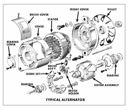
Generators produce Direct Current. Alternators produce "alternating current", or AC. Alternators have the advantage of producing far more current at low speeds than generators, thus allowing more and more accessories in the car. In an alternator, the "field" windings are placed around the spinning central shaft rather than on "shoes" as in the generator. Two iron pole pieces - cast with "fingers" - are slid on the shaft, covering the field winding so that the fingers are interspaced. The fingers on one pole piece form the North poles and the fingers on the other form the South poles. This assembly is called the ROTOR. Surrounding the rotor are a series of windings around laminated iron rings, attached to the alternator's case. This assembly is called the STATOR. The engine's crankshaft spins the rotor.
Direct current from the battery is fed through into the rotor's field coil by using brushes rubbing against slip-rings. One end of the field coil is fastened to the insulated brush, while the other end is attached to the grounded brush. As the pole fields pass through the stator, current is electromagnetically produced (as in the generator) but since the rotor is composed of alternating North and South poles the current produced flows in opposite direction every 180-degrees of rotation. In other words, the current is "alternating".
Why is this more efficient? Well, the stator windings are made up of three separate windings. This produces what is known as three-phase AC. When only one winding is used, single-phase current results (like in a generator). In effect, the alternator produces three times the current of a generator for the same effort on the engine's part. Also, alternators are considerably lighter and smaller than generators.
There's a small problem with alternators, though. AC electricity doesn't work in a car! The car's electrical system - and battery - need DC. Therefore, the alternator's output is "rectified" into DC. This is done by passing the AC into silicon diodes. Diodes have a peculiar ability to allow current to flow readily in one direction only, stopping the flow if the direction reverses. Multiple diodes are arranged in alternators so that current will flow from the alternator to the battery (in one direction only, creating DC) but not from the battery to the alternator.
In actual operation, the voltage regulator senses the battery voltage and overall demand on the car's electrical system. When charging is needed, the regulator applies battery voltage to the stator's brushes and this creates the electrical field for charging. As the system's demand for charging decreases the voltage to the brushes cuts off. All of this occurs many times per minute, with the system turning on and off repeatedly to keep everything at optimum operating efficiency.
Voltage Regulators
As you may recall from last month's article on the function of generators, there is no means of internally controlling the output of one. In other words, the faster it spins the more voltage goes into the car's electrical system. If this weren't controlled the generator would damage the battery and burn out the car's lights. Also, if the generator weren't cut out from the car's circuitry when not running, the battery would discharge through its case.
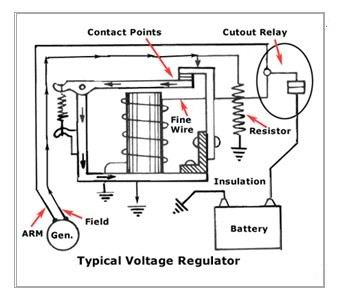
That's where the REGULATOR (commonly called the Voltage Regulator, but that's only one component of the system) comes in. Regulators have seen many design improvements over the decades, but the most commonly used electro-mechanical regulator is the three-control units in one box type. Let's look at how these things work...
Cutout Relay
Sometimes called the circuit breaker, this device is a magnetic "make-and-break" switch. It connects the generator to the battery (and therefore the rest of the car) circuit when the generator's voltage builds up to the desired value. It disconnects the generator when it slows down or stops.
The relay has an iron core that is magnetized to pull down a hinged armature. When the armature is pulled down a set of contact points closes and the circuit is completed. When the magnetic field is broken (like when the generator slows down or stops) a spring pulls the armature up, breaking the contact points.
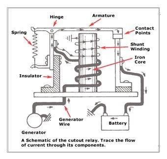
An obvious failure mode is the contact points. As they open and close, a slight spark is generated, eventually eroding the material on the points until they either "weld" themselves together or become so high in resistance that they won't conduct current when closed. In the first case the battery would discharge through the generator overnight and in the second there would be no charging to the system.
Voltage Regulator
Another iron core-operated set of contact points is utilized to regulate maximum and minimum voltage at all times. This circuit also has a shunt circuit (a shunt re-directs electrical flow) going to ground through a resistor and placed just ahead (electrically) of the points. When the points are closed the field circuit takes the "easy" route to ground but when the points are open the field circuit must pass through the resistor to get to ground.
The field coil on the generator is connected to one of the voltage regulator contact points. The other point leads directly to ground.
When the generator is operating (battery low or a number of devices running) its voltage may stay below that for which the control is set. Since the flow of current will be too weak to pull the armature down the generator field will go to ground through the points. However, if the system is fully charged the generator voltage will increase until it reaches the maximum limit and current flow through the shunt coil will be high enough to pull the armature down and separate the points.
This cycle is repeated over and over in real time. The points open and close about 50 to 200 times per second, maintaining a constant voltage in the system.
Current Regulator
Even though the generator's voltage is controlled it is possible for its current to run too high. This would overheat the generator, so a current regulator is incorporated to prevent premature failure.
Similar in appearance to the voltage regulator's iron core, the current regulator's core is wound with a few turns of heavy wire and connected in series with the generator's armature.
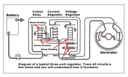
In operation, current flow increases to the predetermined setting of the unit. At this time, current flow through the heavy wire windings will cause the core to draw the armature down, opening the current regulator points. In order to complete the circuit the field circuit must pass through a resistor. This lowers current output, points close, output increases, points open, output down, points close, and so on. The points, therefore, vibrate open and closed much as the voltage regulator's points do, many times every second.
Good and Bad News
Because they are mechanical, voltage regulators are easy to troubleshoot. If you study the function of each of the three parts and how they interrelate, it becomes obvious which part is malfunctioning, depending upon symptoms. That means anyone who understands how everything works can easily troubleshoot problems. That's the good news.
The bad news is that the point gaps and spring pressures determine the voltage/current limits and they are exceedingly hard to adjust. Sometimes it can be done on the car using a voltmeter, but generally it is best to replace the entire regulator assembly when a certain part of it fails. Factory assembly of regulators required relatively sophisticated measurement instruments. Adjusting them by "feel" is a matter of luck, and frequently can result in damage.
Overall, the good news is that regulators are inexpensive and relatively easy to find. Replacement is always a good idea.
What about Alternator Regulators?
The same type of regulator was originally incorporated into alternator-fitted cars and they work in much the same way. However, since some cars used ammeters no current regulator was needed. Therefore, a "single unit" regulator was used to turn on the alternator's stator windings. It was just a regulator without a current regulator section.
It wasn't long thereafter that the automobile companies converted to transistor voltage regulators. Utilizing Zener diodes, transistors, resistors, a capacitor and a thermistor, these regulators maintain proper voltage and current flow throughout the system. Their circuitry operates as fast as 2,000 times per second and they are tremendously reliable. On the other hand, these regulators aren't easy to repair. They are designed to be thrown away and replaced.
Many "solid state" regulators are mounted inside the alternator and are not serviceable other than the ability to set the voltage limits. That's okay, because they work very well for long periods of time. To check their operation, just measure the battery voltage while the engine is off, then when it's running. You should see something between 13 and 15 volts when running. No change in voltage means either the regulator or alternator isn't working, while higher voltage means the regulator isn't properly "regulating."
What about Converting from Generators to Alternators?
Well, that's a double-sided question. We believe such conversions should be done if additional electrical devices have been installed during restoration or major updating of the car. Air conditioning, electric cooling fans, etc. eat up lots of current that can't be easily handled by old generators. Alternators provide three times the current and weigh much less than their old counterparts.
On the other hand, converting to an alternator will affect the car's "period" appearance. It's a personal choice, of course, but one worth considering. We'll be doing an article on a conversion very soon.
Starters
By now you are becoming more familiar with how electricity is stored, generated and regulated in the automobile. It might have occurred to some of you that the electrical system only needs 80 to 100 amps of current for general running, even when all accessories are operating. Why, then, does our battery have a rating of 450 to 750 - and more - amps? Is all this storage necessary?
Yes it is! The main reason for the battery's storage capacity is to operate the starter, and a quick look at the numbers will demonstrate why this is so important:
Let's take a 500-amp-rated battery for example. At 12 volts, this 500 amp battery is capable of putting out 6000 watts (amps X volts = watts, remember?). We need all the wattage we can get to develop enough horsepower to turn the engine over for ignition and one horsepower (or the power necessary to lift 550 pounds one foot in one second) equals 746 watts. Our battery, therefore, puts out just over eight horsepower. That's just enough for a couple hundred revolutions of the engine before the charge is exhausted. If the engine doesn't start by then, well, you know...
Starters are incredibly strong motors that work in a hostile environment. They are the most important part of the starting system, or circuit, consisting of the following:
FLYWHEEL RING GEAR - This is a toothed ring that is fitted to the outside of the engine's flywheel. Matching teeth on the starter motor mesh with this gear in order to spin the crankshaft.
STARTER SOLENOID (Relay) - All cars are wired so that the battery's main cable connects to the starter motor windings (the thick cable is needed for large current flow, right?). This wire must be switched on and off, of course, and it would be costly and inefficient to route it through the ignition switch (not to mention the size of the switch's components required to carry such current!). Consequently, a relay is necessary...
Relays are devices that utilize a central iron core fitted closely to the inside of a coil of wire. When the wire is energized the iron core will be drawn down the length of the coil, the direction dependent upon the direction of current flow. If the relay's iron core is fitted with large, high current-carrying contacts it can be used as a high-current switch. Relays are used throughout cars (for horns, electric fans, air conditioning clutches, etc.) and the most important one is the starter solenoid.
The starter solenoid has very large contacts to carry the battery's full current. Its wire coil is actuated by a smaller current from the ignition switch, at which time the iron core slams down to make contact and turn on the starter motor. Most non-Ford starter motors employ a solenoid built into the motor itself. This type of solenoid not only provides the motor's electrical power but also mechanically engages the starter's drive gear onto the flywheel. It is commonly known as the BENDIX type of solenoid. Such solenoids operate in three stages, the disengaged, partially engaged and engaged. In the disengaged position the drive gear is released and no current is flowing. In the partially engaged stage, current from the starter switch flows through both the pull-in and the hold-in coils. Both coils draw the plunger inward, causing it to pull the shift lever and engage the pinion gear. When the plunger is pulled into the coil all the way, the pinion fully engages the ring gear. When the ring gear is fully engaged, engine cranking begins. When the engine starts the hold-in coil will cut out and the plunger will move out, retracting the pinion and opening the starter switch.
STARTER MOTOR - This is a powerful electric motor that engages the car's flywheel in order to spin the crankshaft. As in all electric motors, the starter is composed of windings of wire that form loops, ending at the commutator segments (remember these from the generator?). The armature coils are mounted on the motor's central shaft (supported with bearings) and the field coils are formed into four or more "shoes", placed inside the steel frame of the starter. Brushes are used to create electrical contact to the commutator segments and when current is fed into two of the four brushes, it flows through all the loops of the armature and shoe windings and out the other two brushes. This creates a magnetic field around each loop. As the armature turns, the loop will move to a position where the current flow reverses. This constant reversal of current flow allows the armature and field coils to repel each other and spin the motor. The greater the current flowing in the coils, the greater the magnetic forces, and the greater the power of the motor.
The copper loops and field windings are heavy enough to carry a large amount of current with minimum resistance. Since they draw heavy amounts of current, they must not be operated on a continuous basis for longer than 30 seconds. After cranking for 30 seconds it is wise to wait a couple of minutes to let the starter motor dissipate some of its heat. Starters heat quickly, so prolonged use can cause serious damage. A typical symptom of overheating starter motors is extremely slow, labored engine-cranking.
Various wiring designs are used in starter motors and one of the most popular is the four pole, three winding setup. Two of the windings are in series with themselves and the armature. One winding does not pass through the armature, but goes directly to the ground. This Shunt Winding aids with additional starting torque. However, as the starter speed increases, the shunt still draws a heavy current and tends to keep starter speed within acceptable limits.
Diagram above shows a typical Bendix-drive, four pole, three-winding starter motor.
Starter motors fail mostly due to overheating. They are placed in a hostile, hot environment and cannot be expected to last indefinitely. Another mode of failure is a shorted or open winding. This exhibits itself as a "dead spot" on the commutator. If a brush lands on a dead spot the motor won't turn at all.
A third failure-mode is a faulty pinion engagement. Sometimes the pinion assembly gets stiff or stuck due to lack of lubrication or wear. Starter motor rebuilding or replacement is required for all of these problems.
Before doing so, however, check to make sure the electrical connections on the starter (and the battery) are clean and tight. Most failures to start are due to loose or corroded battery cable connections or low-current solenoid connections, not to faulty starters.
Ignition Systems
So far in this series we have covered basic DC electricity theory, then batteries, generators, alternators and starters. Adding those together, we have developed an electrical circuit to get the car started and charge the battery, but now we need a circuit to actually run the car. That, of course, is the ignition system and it is comprised of several parts, comprising two distinct systems, the primary and secondary ignition systems. Let's take each one in order...
PRIMARY IGNITION SYSTEM
The primary system consists of the ignition switch, coil primary windings, distributor contact points, condenser, ignition resistor, and starter relay.
Ignition Switch. Your ignition switch does at least three things:
First, it turns on the car's electrical system so that all accessories can be operated. It does so by providing power to the fuse panel (for those components that are controlled by the switch. Some items are independent of the ignition switch, such as headlights, horn, clock, etc.) When you insert the key and turn the switch to the "accessories" position, you are turning on the other devices in the car, such as the radio, heater, power windows, seats, defroster, etc.
Second, in the run position, everything is turned on, plus the engine's electrical components that enable it to run. Most important, it turns on the entire primary ignition system.
Third, when you move the switch to the "start" position it energizes the starter.
Wait a minute! We just learned that the starter takes enormous current from the battery through its thick cable. How can the ignition switch carry so much current if there isn't a battery cable connected to it?
Good question! The ignition switch doesn't carry the necessary current to the starter. It sends a small current to a special device called a Relay that, in turn, allows the starter to crank. We'll discuss that later in this article. Back to the primary ignition system...
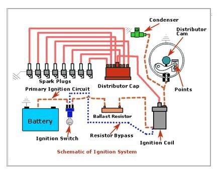
The next component is the coil's primary winding. Inside the coil are two sets of wound wire, comprising of the primary and secondary windings. The primary windings carry battery voltage through and create a large magnetic field inside the coil (this is discussed thoroughly in the section on secondary windings). Although the coil's primary windings receive voltage from the ignition switch, they are actually turned on and off by the distributor's contact points.
The contact points are opened and closed by a cam on the distributor's main shaft. As it spins the cam's lobes move the actuator outward, disengaging the contacts. When the lobe passes, the contacts close, turning on the coil primary windings. The amount of time the points remain closed is referred to as dwell, and is an important factor in engine tuning.
Attached to the points is a condenser, an electrical device (capacitor) that limits current flow through the points to increase their life. The condenser is necessary because the points are opening and closing rapidly, and as they do so the voltage/current is interrupted. This causes an arc, or spark, between the contact points. Over time, this arcing will erode the material on the points and deposit carbon, and eventually the points will not pass current. The condenser acts as a current-absorber to limit the amount of arcing as the points open and close.
The next component is the ignition resistor. It is necessary because ignition coils are designed to step up battery voltage high enough - and fast enough - to keep the engine running at high rpm. That means that, as designed, the coil would produce too much high voltage at low rpm and heat up. Automakers long ago realized that there were two solutions to the problem: using two coils (one for low rpm and one for high) or an ignition resistor. Obviously, the resistor approach is the least expensive and most reliable, so that's what they did. The resistor used varies is resistance as a function of temperature, and limits the voltage to the coil accordingly. As the engine revs up the resistance lowers, allowing more voltage to the coil for fast running, and the reverse happens when the engine slows down. At idle, for instance, only about 7 volts is going through the coil primary windings.
The only time the resistor is out of the circuit is during startup, when the engine needs all the spark it can get. It's bypassed in the ignition switch's start position so that, during starting, the coil gets full battery voltage. Ignition resistors can take many forms, depending upon the manufacturer of the vehicle. Some builders mounted a big resistor on the firewall and some others utilized a special type of wire (resistance wire) running from the ignition switch to the coil. Still others used coils that were built with an internal resistor. None of these is any better an approach than the others, but it's important to know which type you have, and that you have one!
SECONDARY IGNITION SYSTEM
The secondary ignition system consists of the coil secondary windings, distributor cap, rotor, plug wires and spark plugs.
Coil Secondary Windings
So just how does a coil work? Well, the principle of Inductance is the answer. Physics tells us that if you put a certain voltage through a wire (the primary) that has another wire wrapped around it, the second (hence, secondary) wire will receive an "induced" voltage from the first. Furthermore, the "induced" voltage is a function of the number of turns of wire wrapped around, so if you have two coils wrapped around the wire you'll get twice the voltage, and so on. Voltage can be stepped-up and stepped-down using inductance. Transformers are inductance devices, so a coil is a transformer.
Automotive coils generally have secondary-to-primary ratios of 200 to 1. Therefore, a 12-volt input to a coil's primary windings will result in a 24,000-volt output from the secondary winding. That's where the spark plugs get their electricity.
Inductance isn't perpetual motion, nor is it "free energy." There are many "howevers" and other considerations to worry about. The biggest one is the coil's inability to hold the induced voltage once it's been built up. In a very short time the voltage will "bleed of," leading to weak spark. Also, the coil takes a finite amount of time to build the charge up. That's the dwell time, normally defined as the degrees of rotation of the camshaft during which the points are closed. Too little dwell and the coil doesn't have time to charge up fully. Too much dwell and the coil has bled off some charge, causing a weak spark. Hesitation, low power, misfiring, pinging and a number of other conditions are symptoms of incorrect dwell.
Important Note: Since dwell is measured by camshaft rotation and the camshaft runs at one-half the speed of the crankshaft, for every two degrees of dwell an ignition is off, the engine's timing will be off one degree! If an engine needs to be re-timed when it's periodically checked, the points have worn down (thereby increasing dwell). The timing chain hasn't slipped, as so many believe.
Dwell angle has always been set by properly adjusting the ignition point gap. Your car's gap was derived by engineers to approximate the dwell angle, but individual point sets can vary considerably in their mechanical and electrical characteristics. The only way to properly set up ignition points is with a dwell meter.
Distributor Cap and Rotor
The distributor cap is one of the most appropriately-named devices on the car. It's job is to distribute the high voltage pulses [generated by the coil] to the correct spark plug at the correct time. It does this through the rotor. The rotor is keyed to the distributor shaft. On the rotor is a spring-loaded "wiper" arm, whose purpose is to pick up high voltage pulses from the coil. The wiper arm is electrically connected to the rotor's tip.
Inside the distributor cap are metal nipples that are attached to the sockets holding the plug wires. As the rotor moves around its tip comes within about one millimeter of the cap's nipples, whereupon the high voltage charge jumps over. From there it travels through the plug wire to the plug, which is grounded to the engine block. The charge has nowhere else to go but to the plug's electrode, creating a spark.
Plug Wires
Spark plug wires are greatly underappreciated and often overlooked when it comes to maintenance. They are designed to carry 20,000 to 40,000 volts (much more in modern cars) to the sparkplugs without losing the charge, breaking down electrically or "leaking" to ground. They operate in extreme heat and vibration environments.
Plug wires originally were constructed with a central copper conductor, wrapped in various layers of insulation. This was very effective, but when AM radios appeared they caused interference (high voltage creates large electromagnetic fields that in turn cause spurious radio signals. These are picked up by radio sets as static). By the 1950s many manufacturers turned to resistance wires to cure the interference problem.
Resistance wires utilize a central core made up of some flexible material impregnated with a conducting medium, usually a form of carbon, wrapped in insulation. These wires have specific internal resistance that is designed to provide proper spark with minimal electromagnetic interference. Such wires are easily damaged, especially at the ends, where the inner cores are connected to metal "boots."
Resistance wires have a finite lifetime and must be replaced after a specific number of miles or operating hours. Solid-core wires also must be replaced when the insulation becomes cracked or stiff.
Spark Plugs
It never fails. What seems the simplest of things often turns out to be the most complex, and that's true in the case of spark plugs. Looking at a typical spark plug, let's define its various parts:
The terminal is the top of the plug where the wire connects. Under that is a ceramic (insulator) section with ribs molded onto it to reduce flashover. Under that is the crimp, where the metal body begins. Below the crimp are the wrench flats, a hexagonal area that is sized for a specific wrench. Under that is the shell, which is threaded at the bottom to the size (diameter) and reach (depth) of the threaded hole in the engine's cylinder head. The plug ends at the bottom, where there is a ground strap or other device protruding over the central metal core, the electrode. Surrounding the electrode is ceramic insulation to keep it from sparking into the inside of the metal shell rather than at the end ground.
It doesn't end there. Spark plugs are designed with specific heat ranges. That is, the amount of the central insulator/electrode exposed to the heat of combustion. The deeper the electrode/insulator (and the ground piece, of course, extend into the combustion chamber, the "hotter" the plug and the less it extends, the "colder" the plug. Manufacturers specify certain heat ranges for certain conditions, even within the same engine designs.
Plugs also come in Types. "Type" indicates whether the plug's core is a resistance-type (similar in design to resistance wires) or solid-metal core, projected core nose, and single or multiple ground electrode. Depending upon the engine design, plugs may be specified to require a metal gasket between the shell and the threads.
Spark plugs vary tremendously, so it pays to study what your engine requires. Plug manufacturers publish extensive applications manuals that clearly spell out design differences and, most importantly, which plugs will work efficiently in your engine application.
Overview
How well your engine runs is totally dependent upon how well the primary and secondary ignition system components work, and whether they are matched to your engine. Of course, everything depends upon how closely timed the distributor is to the mechanical components of the engine, but that's the subject of another article, How To Tune Your Car.
Conclusion
We've gone through basic theory and major components over the last several articles, so by now you should be fairly comfortable with overall circuitry. Now, we'll cover just a few more common devices and then draw a simple circuit and follow an electron through it. Ready?
Relays:
This was touched-on before but it's worth special attention. Remember that certain devices require considerable current (amps) and that, in turn, require thicker wire. High current devices require big, heavy switches to handle the current. Unfortunately, these would be ugly and expensive, so engineers use relays.
A relay consists of a small coil of wire around a central iron core. When the actuating switch energizes the coil this core moves heavy-duty contacts together, thus allowing high current to be passed to the device. That's how a small switch can control a high-current device.
You already know the starter solenoid is a high-current relay. Other devices that typically utilize relays are the horns, power antenna, air conditioning compressor, power seats, power windows, engine cooling fans, and power tops. Sometimes, headlights and accessory driving lights use them too. It's important to know this because many electrical failures occur in the relays themselves!
Automotive Fuses:
Almost everything in a car is wired through a fuse. Fuses are designed to fail when too much current is drawn through the device. This prevents heating of the wires and subsequent melting of the insulation, followed usually by fire!
Fuses are simple in design. Inside a fuse is a soft wire with a specific cross-sectional thickness. This dimension dictates how many amps can be carried before the wire melts. Too many amps and the fuse fails, saving the rest of the circuit from damage. Pretty neat, huh?
Most of any car's fuses are located in the fuse panel, but some are in-line. In-line fuses are found under the dash and in the engine compartment.
Fusible Links, another kind of fuse, are used in many cars and are almost always found in the wiring harness in the engine compartment. These are molded, single-purpose links in the wire which are designed to melt under extreme conditions (usually a crash which might crush wires together, causing a huge short circuit). Your car's schematic will show their use and location.
Let's look at a fairly typical horn circuit and see how various components are put together to form a working system:
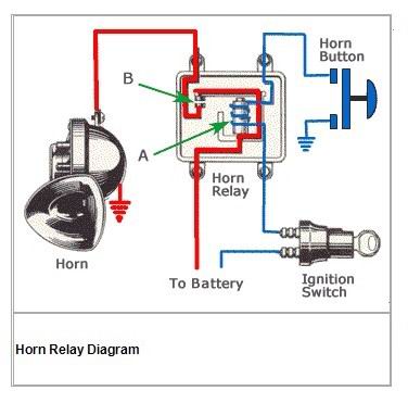
Notice that battery voltage travels through a high current wire (red) through the relay to the horn and also through a smaller wire (blue) through the ignition switch to the relay's low-current coil. The first thing you should be aware of is that the horn circuit is always "hot" or "live" when the ignition switch is turned on and all that's needed is a path to ground.
That path is completed when you push in the horn button. When the button is pushed the ground connection is made, energizing the relay's coil "A". The coil's iron core (in this particular design) pulls down arm, connecting high-current contacts "B". High current then flows from the battery to the horn (the horn is connected to ground because it's mounted to the chassis of the car). See how it works?
Actually, one thing is missing from this circuit. There has to be a fuse somewhere in the circuit! The high-current wire from the battery might go through an appropriate fuse on the fuse panel or there might be an in-line fuse near the horns (it depends upon the producti, on, engineering decisions as to the most economical placement, but your schematic drawing will show its location).
Also, your car's designers might have fused the low-current side of the relay as well. Check the schematic.
Suppose the horns don't work. Where do you start your troubleshooting? Here's a good procedure:
1. Check the fuses.
2. Check for voltage to the horns at the horn connector. Push the horn button or jump the wire to ground to actuate the relay. If you have voltage the horns should be operable, so search elsewhere for the problem.
3. Check for voltage at the horn button. While there, check to be sure the button's contacts touch each other when pushed. If everything's ok, go to the relay.
4. With someone pushing the horn button, check for voltage (on the low-current wire coming from the dash) on the relay. If there is voltage, the relay isn't working, right?
That's right. Now you have isolated the problem to the relay and only two things can be wrong: either the relay's coil isn't energizing (due to an internal broken wire) or the high-current contacts are being drawn together but no current is passing through (remember high-resistance connections?). If the coil is bad the relay must be replaced. If the contacts are charred, file them smooth.
Conclusion:
Automotive circuits are quite simple in design. Remember always that the factory used as little wire as possible, so look at the schematic diagram to see where multiple connections are made. Remember also that your friendly electron travels through several devices on its way to doing its work so you need to systematically trace the path.
Schematic diagrams are printed way too small in the manuals. Take your drawings to a copier that enlarges and blow them up to easily-readable size. Tape all the sheets together into one big drawing an you will find that tracing electrical paths becomes very straightforward.
With a little practice and patience you will no longer fear your car's electrical system.
» More Information 


